This project is a converter for connecting PS/2 keyboards and mice to old Silicon Graphics computers which had a proprietary keyboard/mouse interface. It should work on every non-PS/2 SGI computer with 6pin mini-din, 9-pin D-sub, or 15-pin D-sub keyboard/mouse connectors, such as:
The kicad design files and firmware source code are available in the project github repository.
Under the github releases page you will also find official release archives with pre-compiled firmware, exported gerber files, and PDF schematics, which are not part of the source repository.
Also you might be interested in this video on youtube where I'm showing the board in action and explaining how it works.
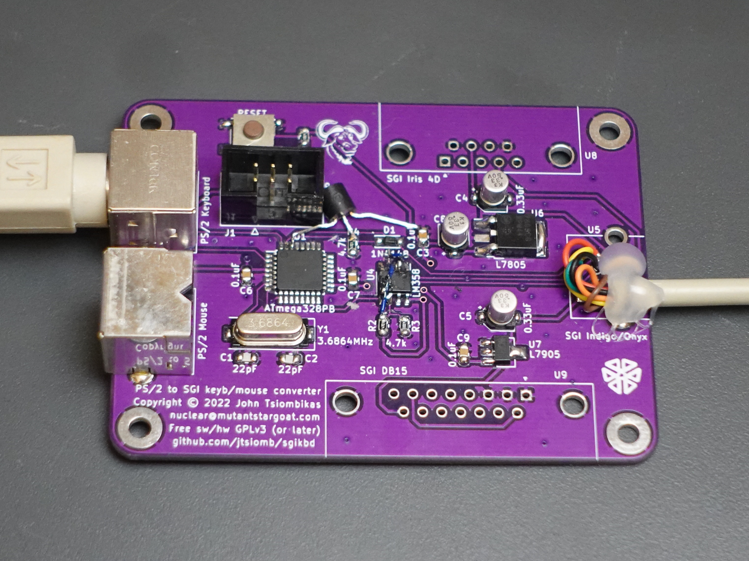
Sgikbd has a 3-pin jumper header (J2), which is used to select the source of the negative voltage supply. Do not leave this jumper open, it will not work. In most cases you should place a jumper at the position labeled "default", to use the negative supply rail from the workstation's keyboard/mouse port. If sgikbd fails to work, it can be because some workstations (notably the R3000 indigo), are missing that negative voltage altogether; in that case place a jumper at the "R3k indigo" position.
If you have revision 2 of the sgikbd board, which doesn't have this jumper, check out these instructions about hacking it to work with the R3000 indigo.
Copyright (C) 2017-2025 John Tsiombikas <nuclear@mutantstargoat.com>
Both hardware designs, and software parts of this project, are released under the terms of the GNU General Public License v3, or at your option any later version published by the Free Software Foundation.
You are free to use, reproduce, modify, and redistribute any part of this project, provided you make any derivative work you release freely available, under the same terms.
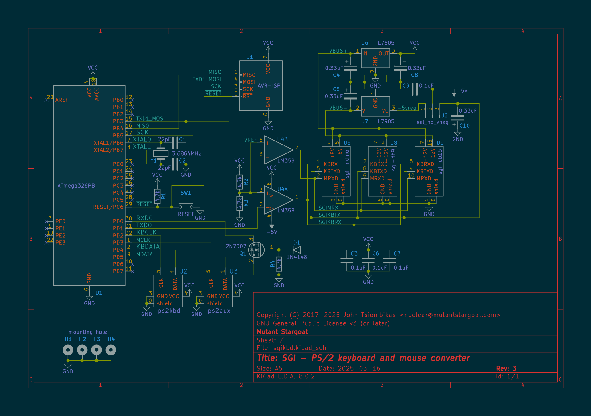
Download the schematic in PDF format.
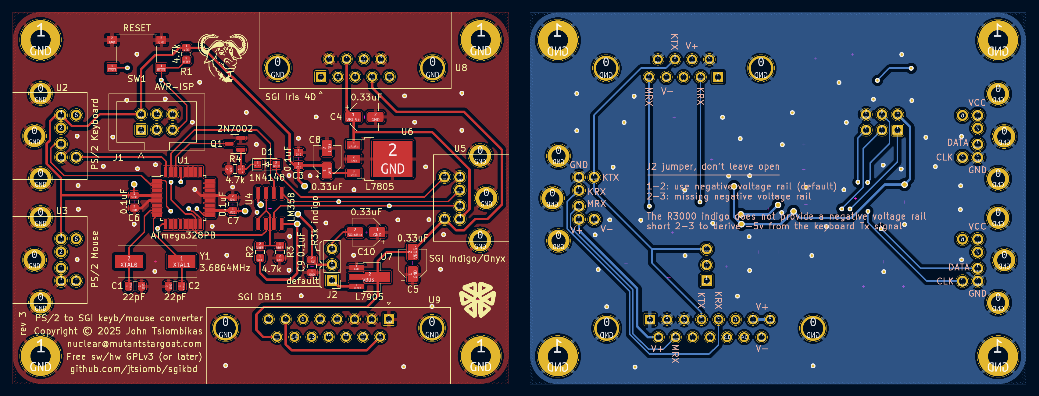
Download gerber files for manufacturing the PCB.
| Description | Count | Designator | Footprint | Mouser part # |
|---|---|---|---|---|
| 22pF capacitor | 2 | C1,C2 | 0805 | 187-CL21C220JBANNNC |
| 0.1uF capacitor | 4 | C3,C6,C7,C9 | 0805 | 187-CL21B104KBFNNNE |
| 0.33uF electrolytic capacitor | 4 | C4,C5,C8,C10 | SMD electrolytic 4.0x5.4 | 647-UWP1HR33MCL |
| 1N4148 diode | 1 | D1 | SOD-123 | 241-1N4148W_R1_00001 |
| AVR programming header | 1 | J1 | 2x3 male pin header 2.54mm pitch (shroud) | 710-61200621621 |
| 2N7002 n-channel MOSFET | 1 | Q1 | SOT-23 | 757-T2N7002AKLM |
| 4.7k resistor | 4 | R1,R2,R3,R4 | 0805 | 603-RT0805FRE074K7L |
| tactile push button | 1 | SW1 | SMD tactile button 6x6mm | 179-TS046670BK160SMT |
| Atmega328PB microcontroller | 1 | U1 | TQFP-32 | 556-ATMEGA328PB-AU |
| Mini-DIN 6pin connector | 3 | U2,U3,U5 | Mini-DIN 6pin through-hole | 571-5749180-1 |
| LM358 opamp | 1 | U4 | SOIC-8 | 863-LM358EDR2G |
| 7805 linear voltage regulator | 1 | U6 | SOT-252 | 621-AS7805ADTR-G1 |
| 7905 linear voltage regulator | 1 | U7 | SOT-89 | 511-L79L05ABU-TR |
| DSUB-9 female connector | 1 | U8 | DSUB-9 female through-hole | 649-ID09S33E4GV00LF |
| DSUB-15 female connector | 1 | U9 | DSUB-15 female through-hole | 649-ID15S33E4GX00LF |
| Crystal 3.6864MHz | 1 | Y1 | SMD HC49-SD | 815-ABLS-3.6864M-T |
| Jumper pin header | 1 | J2 | 1x3 male pin header 2.54mm pitch | 538-22-28-4035 |
Download the BOM in CSV format
Interactive BOM, useful during assembly
To build this board you will have to:
Simply download the gerber zip file from this page, or zip the gerber directory from the latest release archive on github, and upload it to a PCB manufacturer of your choice. I usually use JLCPCB. Another popular choice is PCBWay, and there are of course many more PCB manufacturers out there. JLCPCB charged me 1.5 euros plus shipping for 5 of these boards in 2022. Shipping to europe was about 30 euros.
I usually shop for components from mouser, and for convenience I've included mouser part numbers in the BOM. This means you can just download the BOM CSV file, upload it to mouser, and create a shopping cart with all the necessary components. If you do so, make sure to also adjust the number of each component to something which makes sense. Buying a single transistor or 3 resistors is ridiculous, and it's useful to have spares just in case.
If you don't have experience with SMD soldering, the only slightly tricky part should be the microcontroller. The trick is to use lots of good rosin flux, a flat-tipped soldering iron with temperature control, and good thin (~0.5mm) rosin-core solder. Tack two opposite corner pins first, then drench in flux, add a bit of solder to the iron tip, and drag it slowly and gently along the pads. If you introduce any shorts, simply clean the iron tip thoroughly, add more flux, and pull the excess solder out with the iron tip.
The rest of the components should not pose any trouble, when in doubt, use flux. Just populate the smallest components first, before the larger ones, to have space to maneuver.
Some PCB manufacturers also offer prototype assembly services. I haven't used any of them myself, so this is untested and experimental, but I've uploaded the necessary files required by JLCPCB to assemble sgikbd boards. If you try ordering pre-assembled boards with these files, please email me to let me know how it went. Beyond the gerbers, you'll also need the following two files:
Note: these do not include the mini-din6 connectors, which were not available from JLCPCB when I went through the process. So if you use these files without further modifications you'll have to source and solder those manually.
If you want to compile the firmware yourself, go into the fw directory, and
type "make". You will need to have the GNU AVR toolchain installed: gcc-avr,
avr-libc, and GNU make.
Alternatively you can just use the pre-compiled firmware image
fw/sgikbd from
the release archive.
For programming the microcontroller with the firmware image, you'll need
"avrdude", and a suitable AVR programmer. Connect the programmer to the 6-pin programming
header on the board and to the computer, and type make program and
make fuses.
The "program" and "fuses" rules in the Makefile are written for
Lady Ada's USBtinyISP
programmer, which is what I'm using, so you might need to modify the command line
slightly to match yours. Probably only the "-c usbtiny" part needs to change.
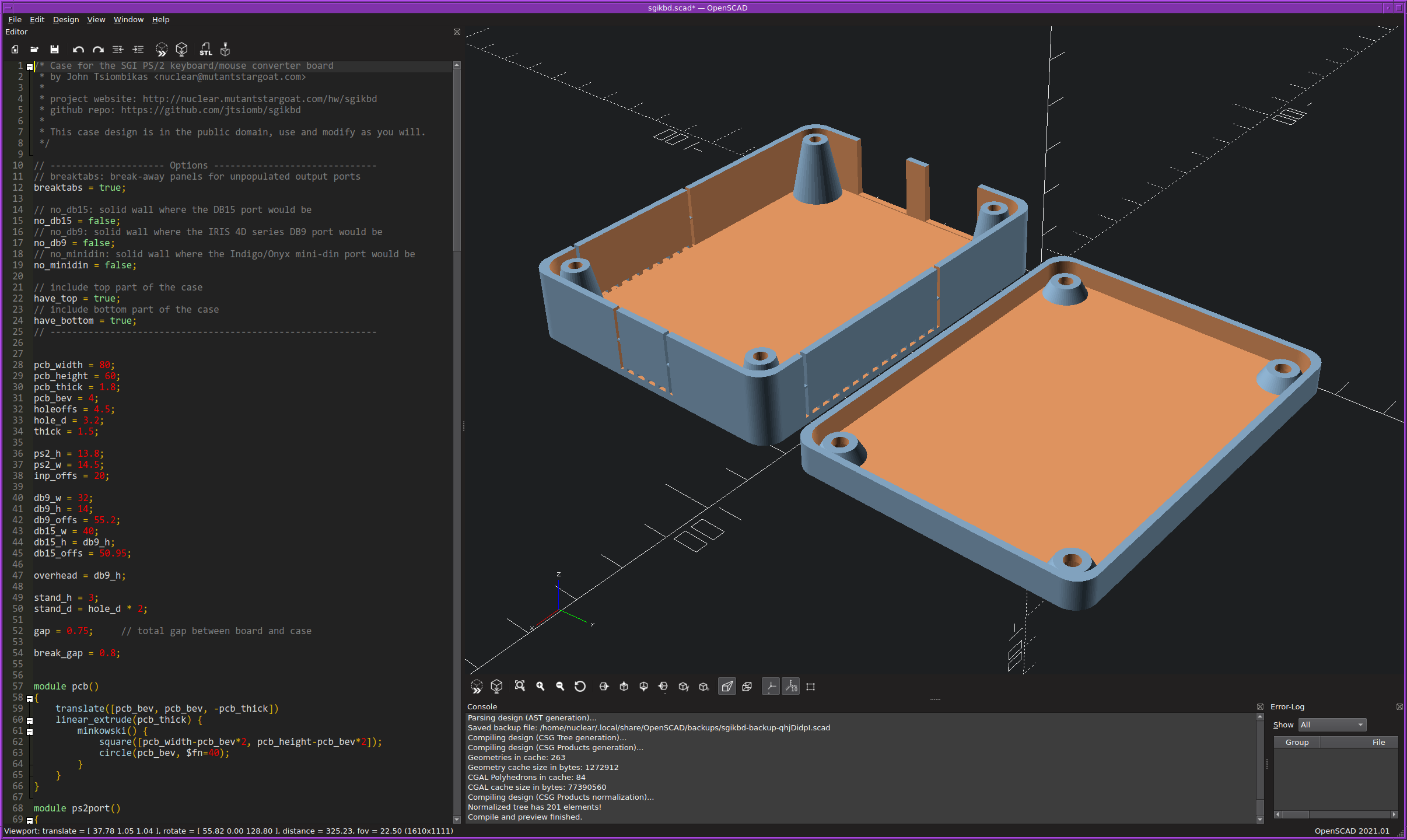
There's also an enclosure design for the sgikbd board, designed for 3D printing.
You can find pre-exported ready-to-print STL files in the release archive, or open
the case/sgikbd.scad source file in
OpenSCAD and export to STL yourself. Make sure
to check case/README.md for details on various options you can set to
customize the case.