If you don't care about the theory, feel free to jump straight to the instructions.
It is reported by multiple users of sgikbd, that it doesn't work with R3000 indigos, because contrary to what the the SGI documentation I used while designing the sgikbd states, they don't provide the -8v supply voltage on the keyboard/mouse port.
| KEYBOARD CABLE PINOUT | ||
| Pin | Signal | Description |
| 1 | KRCD | Keyboard Receive |
| 2 | MRCD | Mouse Receive |
| 3 | GND | Ground |
| 4 | +8Vdc | Power |
| 5 | KTXD | Keyboard Transmit |
| 6 | -8Vdc | Power |
sgikbd uses the -8v rail, regulated to -5v by a 7905, to power the LM358 opamp which inverts and performs level translation for the data transmitted to the workstation.
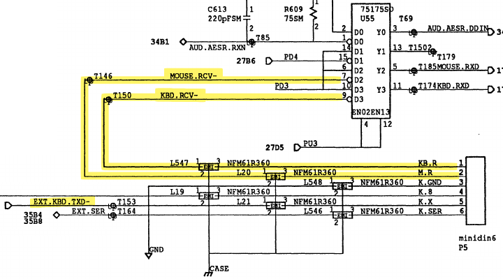
Lacking a -8v supply, we could derive the necessary -5v for the opamp by tapping into the "keyboard transmit" data line. That line is used by the workstation to send commands to the keyboard during initialization, and to toggle lock lights. At all other times, it's idling at a steady -5v level (logic 1).
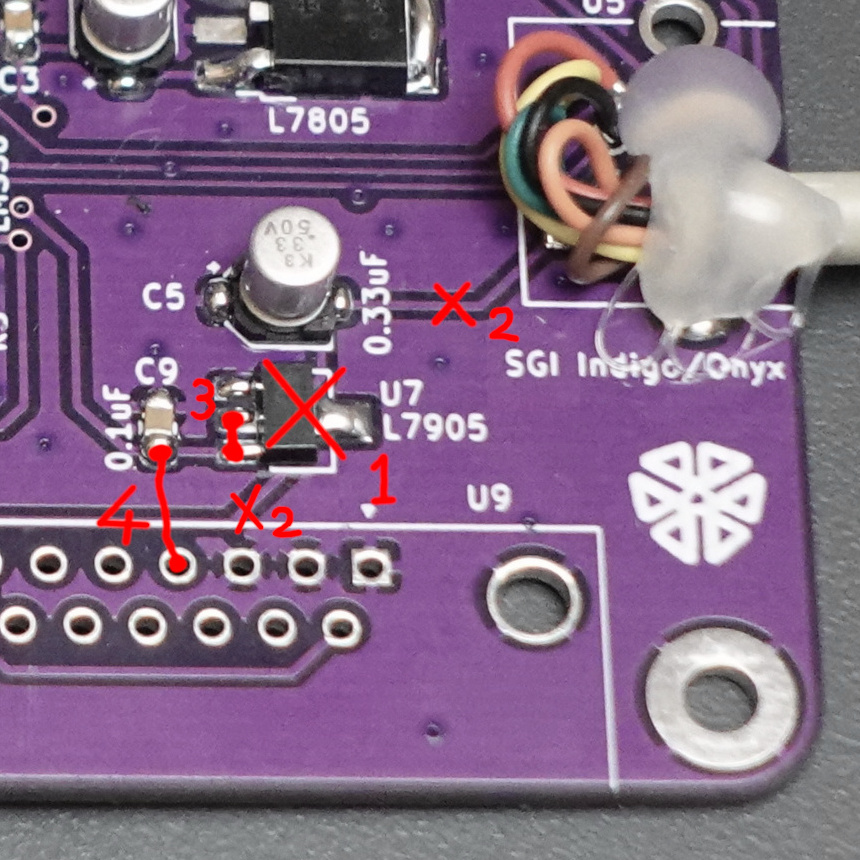
The idea is to remove the 7905 regulator, and use its existing capacitors to store charge while the line is idling at -5v, to smooth out momentary transitions to +5v when the workstation is transmitting. Then just use that smoothed input line as a negative supply rail to the opamp.
The only potential risk involved is for the opamp to draw too much current from the KTXD line, damaging the RS423 output drivers. To determine if that's possible we need an indication of the maximum current drawn by the opamp during normal operation.
The output of the opamp is fed into a 75175 line receiver IC on the workstation side, which has high-impedance inputs. This means that the opamp isn't doing any amplification really, and we can approximately expect it to draw little above its quiescent current.
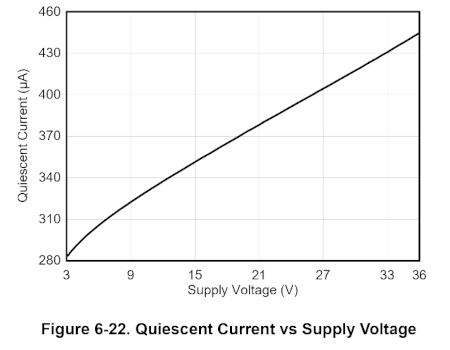
According to the datasheet, the LM358 quiescent current for a supply voltage of 10v (-5v to 5v) is approximately 330μA per amplifier, so 660μA for both. Double that to leave a good margin for the maximum current, and we end up with 1.3mA, let's call it 2mA to leave even more room.
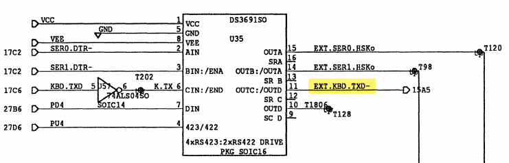
The KTXD line is driven by a ds3691 line driver. According to its datasheet, first of all it has short-circuit protection for source and sink outputs, so even if we exceed its capabilites we shouldn't be able to damage it. But more importantly, it states that its output current can go up to 80 to 150 mA, which is at least an order of magnitude higher than our maximum current draw figure, even if we quadrupled it.

The instructions for performing the hack are very simple, and slightly simpler if done before assembly, because you can skip step 1 if you have not already soldered the -5v regulator.
... step 5: drop me an email, to tell me how it went.