The purpose of emurom is to make it fast and convenient to hack code in ROMs without having to repeatedly remove and reprogram an actual ROM chip.
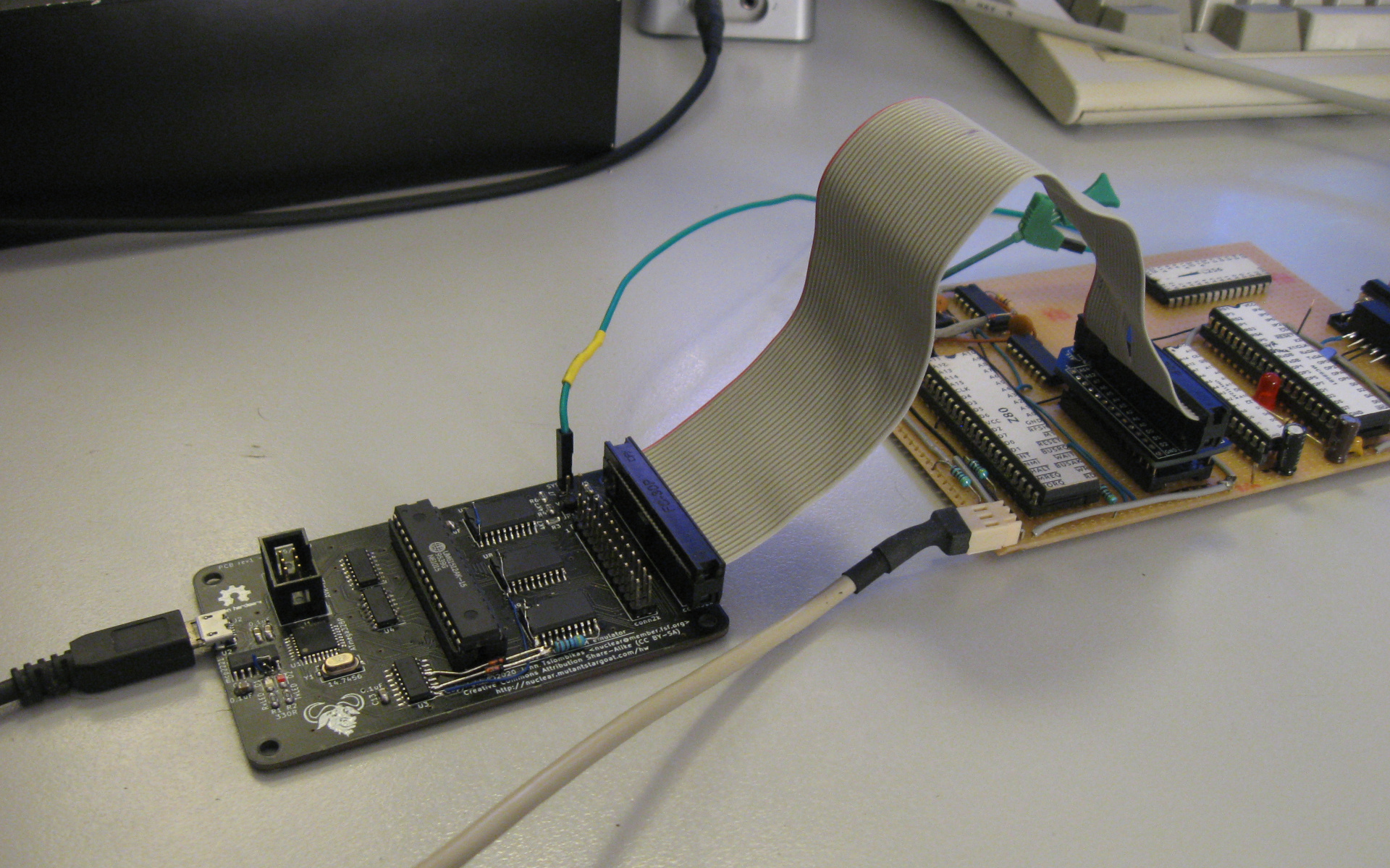
Emurom is a board which connects through USB to a host computer, and can be connected in place of a parallel ROM chip on a target device. It acts as a ROM chip, but holds its data in a static RAM, which can be updated at any time through the USB connection. Optionally it can provide power (5v) to the device by shorting a jumper, and it also has a lead to clip to the reset signal of the target device, to automatically reboot it when a new ROM image is uploaded.
Hardware design (kicad) and source code (firmware/host program) can be found in the emurom git repository on github. Grab a copy with:
git clone https://github.com/jtsiomb/emurom
Or download the release archive which also includes the schematic PDF, gerbers for PCB manufacture, datasheets for all the components, and pre-compiled binaries for the firmware and host program:
Latest release: emurom rev2 (mirror)
Copyright (C) 2020 John Tsiombikas <nuclear@mutantstargoat.com>
All hardware designs in this project are free/open hardware. Feel free to manufacture, sell, use, modify and/or redistribute, under the terms of the Creative Commons Attribution Share-Alike license (CC BY-SA).
All software in this project (firmware and host upload program) are free software. Feel free to use, modify and/or redistribute under the terms of the GNU General Public License version 3, or at your option any later version published by the Free Software foundation. See `LICENSE.sw` for details.
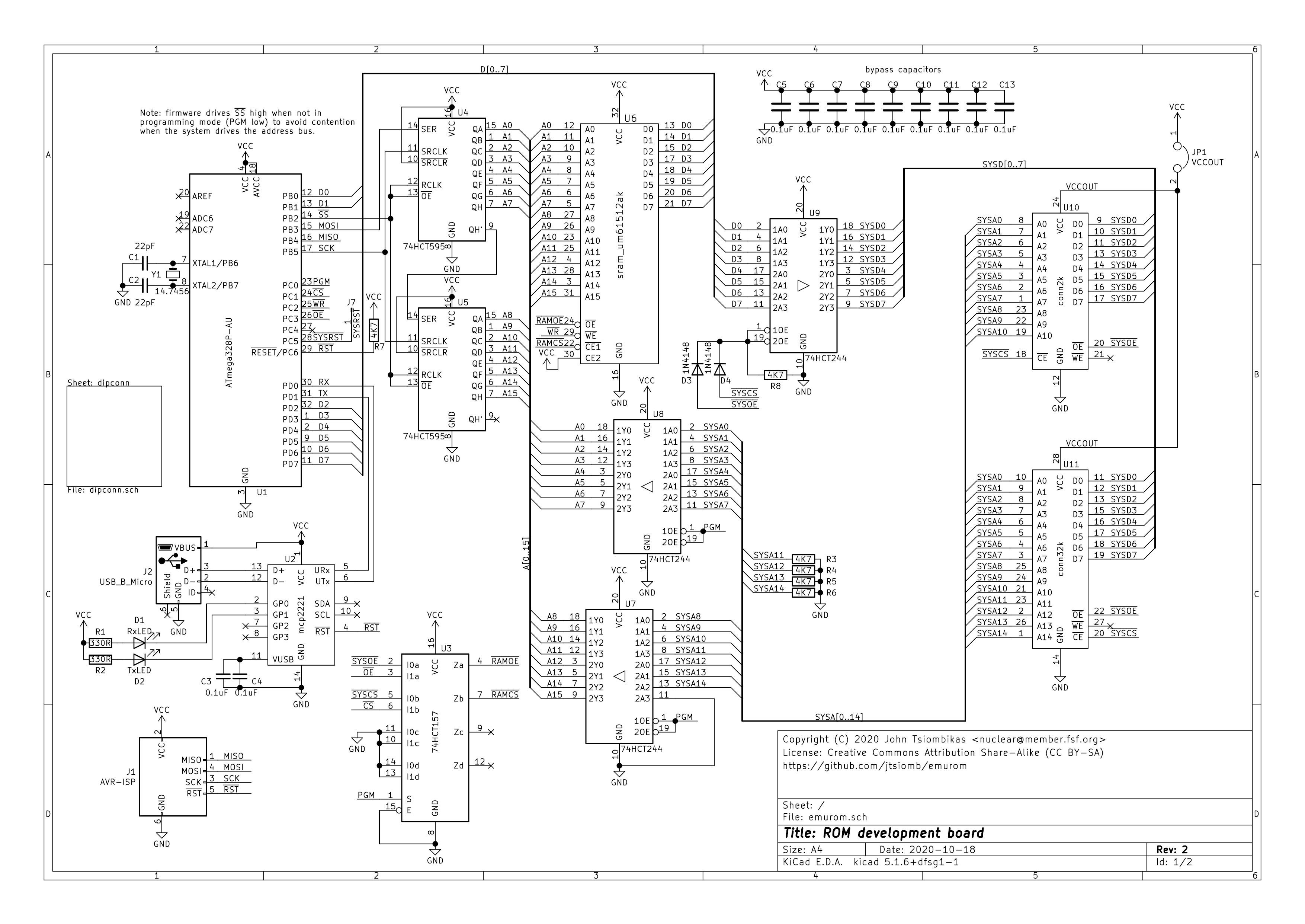
Emurom rev2 schematic in PDF format.
Gerber files for manufacturing the PCB.
Preview of the printed circuit board revision 2 with the ground planes removed for clarity:

To build emurom, you'll need the following components:
| # | name | description | package |
|---|---|---|---|
| 1 | U1 | ATmega328P AVR microcontroller | TQFP 32 |
| 1 | U2 | MCP2221 USB-serial converter | SOIC 14 |
| 1 | U3 | 74HCT157 quad 2-1 multiplexer | SOIC 16 |
| 2 | U4,U5 | 74HCT595 8-bit shift register w/3-state output | SOIC 16 |
| 1 | U6 | UM61512AK 64k static RAM (or other similar 64k SRAMs) | PDIP 32 |
| 3 | U7,U8,U9 | 74HCT244 octal 3-state buffer | SOIC 20 |
| 2 | C1,C2 | 22 pF ceramic capacitor | 0805 |
| 11 | C3-C13 | 0.1 uF ceramic capacitor | 0805 |
| 2 | R1,R2 | 330 Ohm resistor | 0805 |
| 6 | R3-R8 | 4.7 kOhm resistor | 0805 |
| 2 | D1,D2 | LED | 0805 |
| 2 | D3,D4 | 1N4148 signal diodes | 0805 |
| 1 | Y1 | 14.7456 quartz crystal | 7.6x4.1mm SMD |
| 3 | JP1-JP3 | 2-pin male header (jumper pins) | |
| 1 | J1 | 6-pin (2x3) male header or IDC connector 2.54mm pitch | |
| 1 | J2 | molex 105017-1001 micro-USB (type B) connector | |
| 1 | U10,J3 | 24-pin (2x12) male header or IDC connector 2.54mm pitch | |
| 1 | U11,J5 | 28-pin (2x14) male header or IDC connector 2.54mm pitch | |
| 1 | J7 | 1-pin male header |
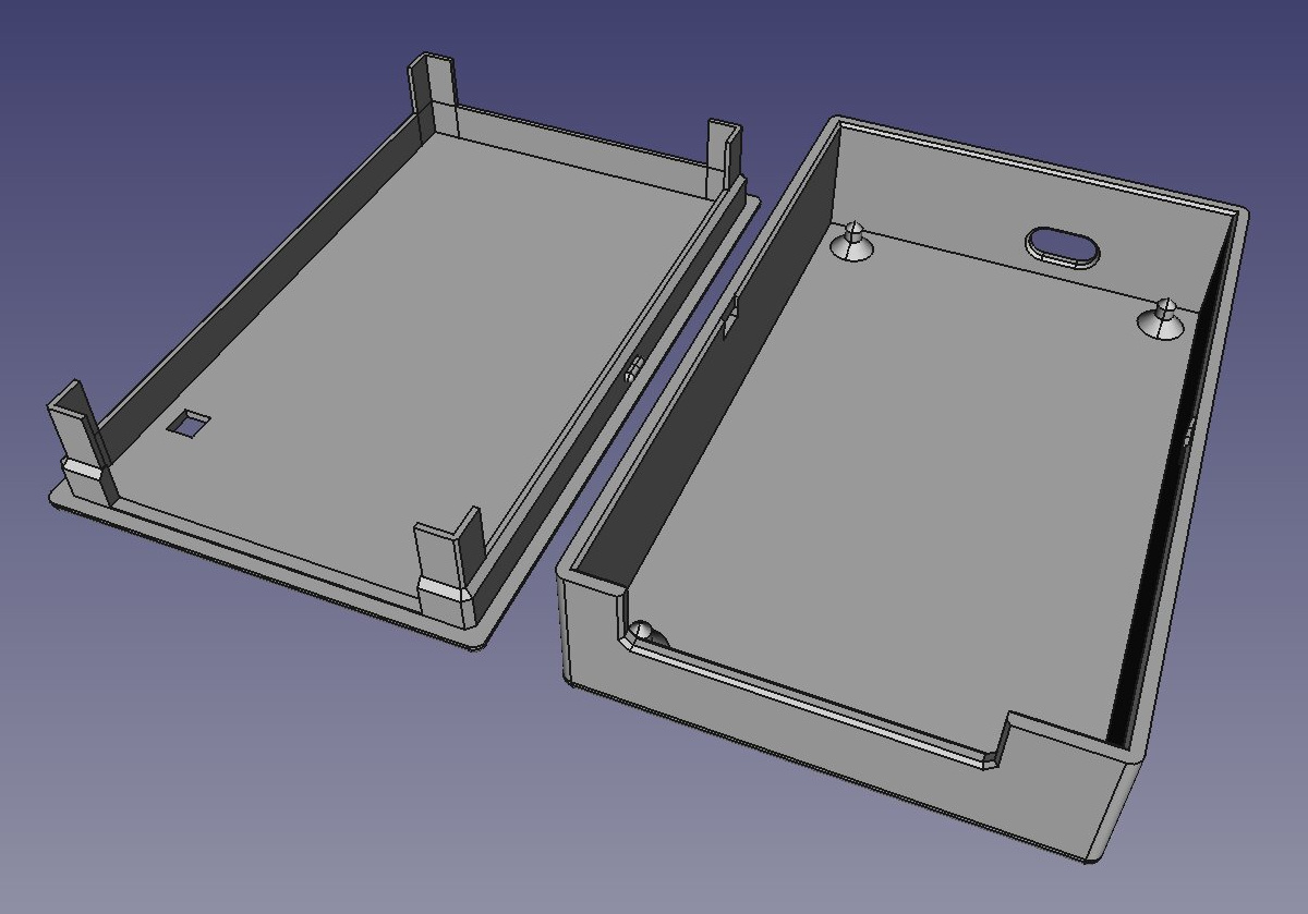
There's also a case you can 3D print to put the emurom board inside. The archive includes the FreeCAD project file, and 3D-printable geometry in STL format for the top and bottom parts.