John Tsiombikas (Nuclear / Mindlapse)
7 July 2020
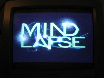
Continuing from the first hack where I painted the screen red, the next step would be to display a static image on screen. The SNES PPU (Picture Processing Unit) supports 8 different video modes with a mix of capabilities and tradeoffs.
The "Retro Game Mechanics Explained" channel on youtube has a very nice overview of all the SNES video modes and their tradeoffs in these two videos:
In fact the whole SNES hardware playlist is highly recommended.
I decided to start with mode 2, which is very much a middle of the road mode, providing a cross-section of SNES graphics features, such as 2 background layers with a very typical 16 colors pixel format, and the ability to define per-column scrolling offsets which I'd like to try out next.
In order to show a picture on screen in mode 2, I had to do the following:
img2snes reads a 4bpp PNG image (later I'll add support for 2bpp and 8bpp
conversions as well), and outputs tile data, a tilemap, and a colormap in the
form of ca65-compatible assembly data declarations, in the format required by
the SNES PPU.
img2snes processes the image in 8x8 pixel blocks, emiting unique tiles, and
tilemap entries as it goes along. If a tile is identical to some existing tile,
the new tilemap entry refers to the existing tile. Finally the tile pixels are
converted to the bitplane format expected by the SNES PPU.
In 4bpp modes each tile is laid out in memory in pairs of bitplanes, one pair after the other, and each pair of bitplanes is scanline-interleaved. So for instance if a tile is to be placed in video RAM starting from address 0, then the first bits of all 8 pixels of its first row form a byte placed at address 0, followed by the second bits of all 8 pixels of its first row (remember: video RAM is word-addressed, so address 0 contains two bytes). At address 1, a byte with the first bits of the second row are expected, followed by a bytw with the second bits of the second row. And so on until all 8 rows (16 bytes) of the first bitplane pair of the tile are placed. Then at address 8 (16 bytes from the start), the second pair of bitplanes is laid out in exactly the same way, but with the third and fourth bits instead of the first and second.
+----------+-----------------+-----------------+
|word addr | word first byte | word second byte|
+----------+-----------------+-----------------+
|    0     |  1st row bit 0  |  1st row bit 1  | \
|    1     |  2nd row bit 0  |  2nd row bit 1  | | bitplane pair [0,1]
|   ...    |      ...        |       ...       | |     (16 bytes)
|    7     |  8th row bit 0  |  8th row bit 1  | /
|    8     |  1st row bit 2  |  1st row bit 3  | \
|    9     |  2nd row bit 2  |  2nd row bit 3  | | bitplane pair [2,3]
|   ...    |      ...        |       ...       | |     (16 bytes)
|    15    |  8th row bit 2  |  8th row bit 3  | /
+----------+-----------------+-----------------+
I decided on the following video RAM layout:
word addr | data         | required size
----------+--------------+-------------------------------------------------
   0000h  | BG1 tilemap  | 2kb (32x32 tile refs, 2 bytes each)
   1000h  | tile data    | ~16kb (477 unique 8x8 4bpp tiles, 32 bytes each)
----------+--------------+-------------------------------------------------
Background data (tilemaps) can be placed with 1k-word granularity, by setting
bits 2-7 of the corresponding BGxSC register. Bits 0-1 of the same register
define the tilemap size:
Tile data can be placed with 4k-word granularity, by setting the 4 high bits of
the video ram address in the appropriate nibble of the BG12NBA or the BG23NBA
register (BG1 tiles at the low nibble of BG12NBA). Of course tile data areas
may overlap and their tiles be shared by multiple backgrounds as needed.
Video memory is not mapped to the CPU address space. To write data into Video
memory, first we have to write the destination (word) address to VMADDL/VMADDH
and then write the data to be placed at that address to VMDATAL/VMDATAH.
After that (assuming we've set up VMAINC correctly), the address
is automatically incremented, and the next write to VMDATAL/VMDATAH transfers
a word to the next address, making it easy and efficient to transfer blocks of
data, without having to set the address for each word explicitly.
Writing to video memory can only be done during video blanking periods (horizontal blanking, vertical blanking, or forced blanking).
If data need to be updated continuously at runtime, it's best to use DMA to
transfer all the necessary data as quickly as possible during vblank. But for
this write-once at initialization time scenario, there's no reason to muck with
all that. While keeping forced blanking on, I just run a copy loop on the
processor to transfer the data a word at a time. Specifically I wrote a generic
copy_vmem routine, which expects the following arguments on the stack:
destination vmem address (in words), source address, and number of bytes to copy
(must be even, since it always has to copy words ot video ram). Abusing the
65816 pea (push effective address) instruction to push arbitrary words onto
the stack, makes calling it as easy as:
        pea logo_tiles_width * logo_tiles_height / 2  ; bytes to transfer
        pea logo_tiles                  ; source tile data pointer
        pea vmem_tiles_offs     ; vmem dest address: 4096 (in words)
        jsr copy_vmem
        rep #$20
        .a16
        pla
        pla
        pla
        sep #$20
        .a8
The copy_vmem routine, uses a neat trick I've read here:
http://6502org.wikidot.com/software-65816-parameters-on-stack
The 65816 allows the "zero page" (which is called "direct page" on the 65816)
to be moved anywhere in the address space, by setting the D register. This
makes it very convenient to use the D register essentially as a stack frame
pointer, and access arguments on the stack and local variables simply with
zero-page+index addressing modes.
Of course the D register must be saved first, and restored before returning
from the function:
    ; function entry (assumes 16bit accumulator mode)
    phd         ; save D
    tsc         ; C (16bit accum) <- S (stack pointer)
    tcd         ; D <- C
    ...
    ; function exit
    pld         ; restore original D
    rts
Having done that, the stack frame (assuming no local variable space), becomes:
zero page |
address   |               item
----------+--------------------------------------
    00    | empty space for the next push
    01    | saved previous contents of D register
    03    | return address
    05    | \ arg1: destination vmem address
    06    | /
    07    | \ arg2: source address
    08    | /
    09    | \ arg3: size in bytes
    0a    | /
----------+--------------------------------------
So the complete video memory copy routine is the following:
        ; copy_vmem(vmem_offset, src, num_words)
copy_vmem:
        rep #$30        ; 16bit accumulator and index registers
        .a16
        .i16
        phd             ; save d
        tsc             ; and make it point to the stack
        tcd
        sep #$20        ; restore 8bit accum
        .a8

        lda #$80        ; auto incerment after wiriting high byte
        sta REG_VMAINC
        lda $5          ; dest addr low byte
        sta REG_VMADDL
        lda $6          ; dest addr high byte
        sta REG_VMADDH
        ldy #0
@loop:
        lda ($7),y      ; A <- *(srcptr + Y)  (low byte)
        sta REG_VMDATAL
        iny
        lda ($7),y      ; A <- *(srcptr + Y)  (high byte)
        sta REG_VMDATAH
        iny
        cpy $9          ; compare Y with arg3
        bne @loop

        pld
        sep #$10        ; back to 8bit index registers
        .i8
        rts
There's nothing more to it really. After copying the tilemap and tile data to
video RAM, and setting up the palette (which I won't go into because it's
trivial: write index to REG_CGADD, write data to REG_CGDATA twice, see
cmap_loop in test.asm), the only thing left to do is set up the PPU
correctly to display the image.
        setreg REG_BGMODE, $02      ; mode 2, 8x8 tiles
        stz REG_BG1SC               ; BG1 tilemap at 0
        setreg REG_BG12NBA, $1      ; BG1 tiles at offs 8kb (4k-words)
        setreg REG_TM, $1           ; main screen: BG1
Setting bit 1 of REG_TM ("Through Main register) routes the graphics from BG1
to the "main screen".
Really the most interesting thing about all this is how to convert the data to
what the SNES PPU expects. Feel free to go through the img2snes source code
for that, refering back to the diagrams above. Especially focus on the
functions: wrtiles, wrtilemap and wrpalette in img2snes/src/main.c.